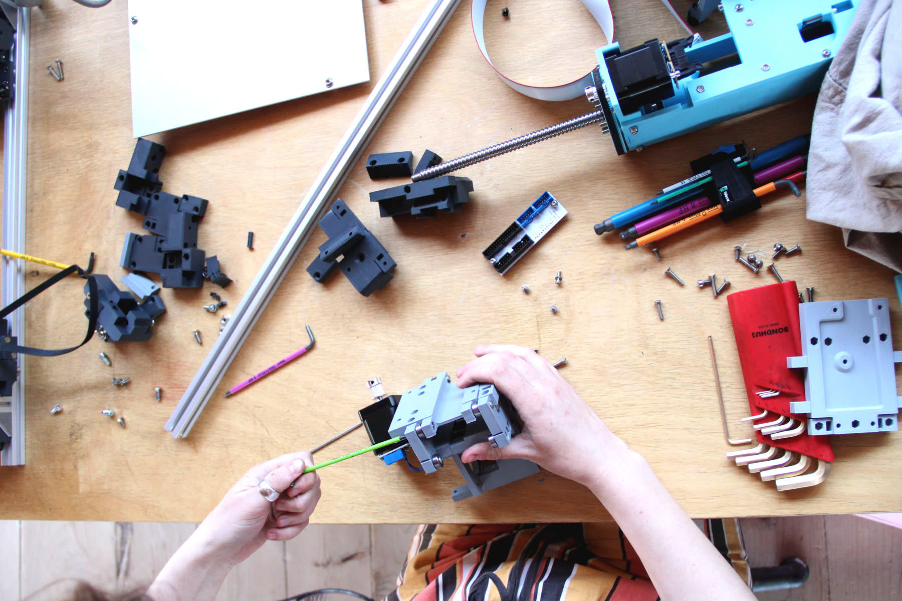
Building Clank(s)

CAD Access
I’m going to keep this very simple for the time being; CAD for both machines will be available below in embedded Fusion360 windows (that will allow you to pull the models into your own instance of Fusion). Details BOMS are too much work to maintain at the moment: the models are fairly complete, please use those as reference.
Clank-Stretch
Get Clank-Stretch as an .f3z
Get Clank-Stretch as a .step
Clank-Tall
Get Clank-Tall as an .f3z
Get Clank-Tall as a .step
Required Tools
You don’t need much to start building one of these. Here’s a list of everything that is strictly necessary to build either Clank:
- any FDM 3D printer; the Ender 3 Pro (cheap) and Prusa i3 MK4 (better) are great options, costing $300 and $900 respectively
- a set of metric allen keys
There are a few things that make this easier - but aren’t required:
- a deburring tool (to take brims off of printed parts)
- a pliers-style wrench, I use
Knipex 86 03 180- besides being one of my favourite tools of all time, it’s wonderful when inserting nylon hex nuts into printed parts. there’s a lot of that. - a set of M3, M4 and M5 taps
I typically keep a stock of extrusion in 2 meter lengths, then cut it to size. But Misumi is great in that you can specify for delivery of cut-to-length parts; you can even ask them to tap the ends for you. For example the misumi part number HFS5-4060-735-TPW specifies at 40x60 extrusion profile (5-series) that’s cut at 735mm. Their precision is pretty good, I’ve checked (to 0.1mm is reasonable to expect). The TPW here specifies that ends are fully tapped; this is how I spec them in the BOM to save you some time.
If you want to cut your own extrusions, you’ll also need:
- a miter saw (!) any carpentry saw will do, go slowly. you can get non-ferrous metals blades if you prefer being fancy
That’s about it. Done wisely, my bet is that you could bootstrap yourself a whole tiny shop (4x8’ multipurpose clank, fdm 3d printer, hardware kit, basic tools) for about $1500 all-told, not a bad start.
Printing Parts
There is admittedly a fair amount of printing required to make these machines, maybe ~ 40 hours or so each. Every part has at least one solid planar face that should be oriented towards the printer’s bed; hopefully that’s easy to identify.
I print in PLA, though it (shouldn’t) matter too much.
If you want a stiff machine, print everything solid, or aruon 90% infill with a few more perimeters than normal.
Here are the settings I use, some of them are important:
| Setting | Parameter | Notes |
|---|---|---|
| Nozzle Diameter | 0.4mm | Standard |
| Layer Height | 0.2mm | Structures are fairly low-res (blocky) so resolution isn’t too important. This increases speed |
| Combine Infill | Every 2 Layers | This speeds things up, I would suggest more but the nozzle is only 0.4mm in diameter, so here’s the limit |
| Number of Perimeters | 4-5 | Defaults are normally 2-3. This slows things down, but I prefer the integrity. |
| External Perimeters First | Yes, turn this feature on | Slic3r lets you specify this in expert mode in the layers and perimeters tab. This helps the printer actually hit the geometry specified in the file; it biases polymer squish to the inside of a part, to the detriment of overhangs (that’s why it’s off by default) |
I’ll bet you can have success with almost any print settings, but I thought I would include my setup anyways.
There are some things with GT2 teeth printed in; for those I turn the external perimeter speed way down, like 10mm/s, this improves the fidelity of the profile and makes belts grip better.
Assembly
My strategy here is to publish thorough CAD models and then leave order-of-assembly up to the reader. I see that’s a little bit rude, but I think it’s also better than nothing. I hope to link to others’ build logs in the future.
As always, GLHF !